Toolbar for Analysis
Basic toolkit: mosaic tool, reclass toolset and tools

Mosaic Tool
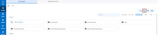
This tool allows the user to mosaic by manually choosing cutlines between images before mosaicing.
Click  icon on toolbar to start use tool:
Create
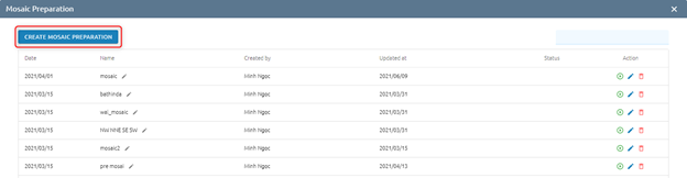
Users want to create mosaic preparation manually with given choices.
Step 1: Click Create Mosaic Preparation button
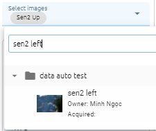
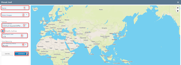
Step 2: Type data:
Type Name
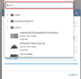
Select images from list images, at least 2 images (Search image from list)
Select cutline method
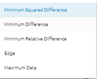
Minimum Squared Difference: A cutline is determined in each overlapped area between two adjacent images, with minimum square difference of gray values at the same locations of the region.
Minimum Difference: A cutline is determined in each overlapped area between two adjacent images, with minimum difference of gray values at the same locations of the region.
Edge: Provides better output in urban-area mosaicking, or in images containing many linear features. The objective is to avoid placing cutlines across linear features.
Maximum Data: Places cutlines on the boundary of the real image pixels, meaning that NoData pixels will be ignored when the image boundary is determined.
Note: Avoid placing cutlines on any of the following:
Buildings or man-made features, because they can lean in different directions in the imagery
Large bodies of water, because waves and the color of the water can differ among the various images
Areas that are significantly different in color and texture, such as forests and cultivated land, because they, too, can differ image to image
Check Simplify Cutlines, if not check, skip (5)
Type Simplification Level
Select Color Balancing Method: Color balancing evens out the color contrasts from one image to another to reduce the visibility of the seams and produce a mosaic that is appealing visually. There are 4 methods:
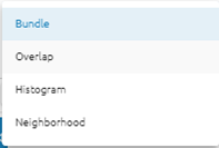
Bundle: firstly, all overlapping image areas after removing anomalies in the data will compute the statistics. A bundle color adjustment (both the mean and sigma of the brightness and contrast) is applied to minimize the overall difference between all overlapping areas. Secondly, the remaining differences are modified with dodging.
Overlap: computes the color-balancing histogram using only the pixels in the overlapping area of the images being added to the mosaic file.
Histogram: Builds histograms for each image starting from the center of the mosaic, determines the optimum radiometry for the input image from the data then applies the transformation to the entire image.
Neighborhood: using all surrounding images to modify the gain and bias of the histogram, regardless of their z-order (based on sorting order) and works iteratively to modify neighboring pixels.
Click Generate button
After generating, a task will be created. Wait for task success, mosaic preparation will be created. Please back to the Mosaic Preparation page to check.
Search
Users want to search mosaic preparation by name in the list. Type name in search input -> Enter
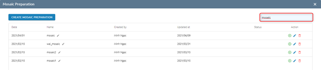
=> Return list contains the type name.
Edit
Step 1: Click icon

Step 2: You can:
Move layer image by drag
Highlight by click layer or click image directly
Add to map
Zoom
Edit: Click image directly on map -> Edit -> Click icon to save
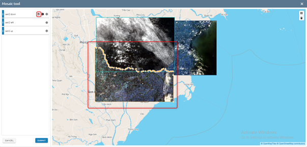
Step 3: Click Submit button to run prepare mosaic or Back to save change.
Rename
Users want to Rename mosaic preparation names. Click pen icon:
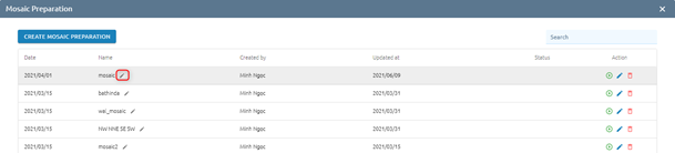
Type new name -> Click Save button
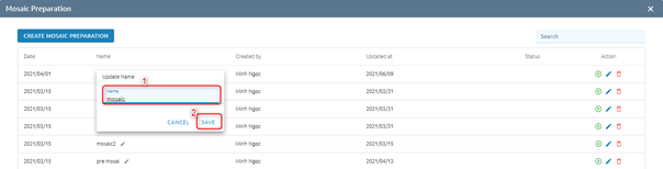
=> Name is changed.
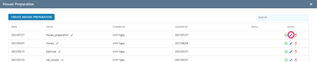
Run
Users want to run mosaic preparation to create mosaiced images.
Step 1: Click  icon to run:
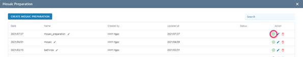
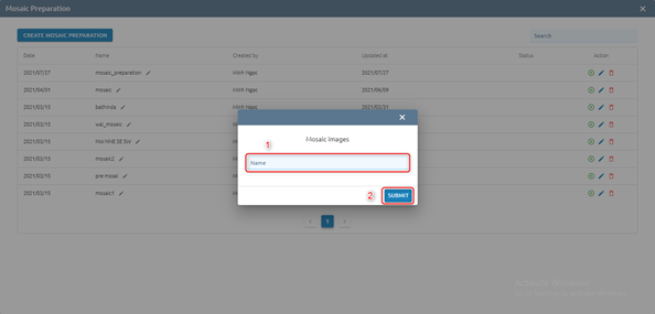
Step 2: Type Mosaic image name -> Click Submit button
Step 3: Confirm pay cost
=> Task will be created in Tasks, wait task success, check result in Imagery.
Delete
Users want to delete Mosaic Preparation. Click icon of Mosaic Preparation you want delete. Then Click the Delete button to confirm delete.
Reclass Toolset
Reclass toolset will reclassify (or change) the value in a raster- a range of value pixels will be reclassified or a single pixel (unique) will be assigned to another value.
You can choose image first, then click  icon or click icon, then select image.
Choose image -> Click
icon:
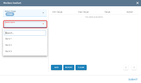
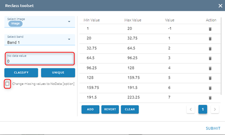
Step 1: Select band (Only one, you can search if there are many bands)
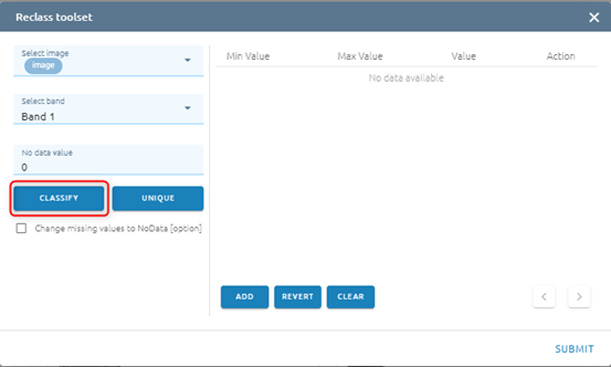
Step 2: Click Classify button
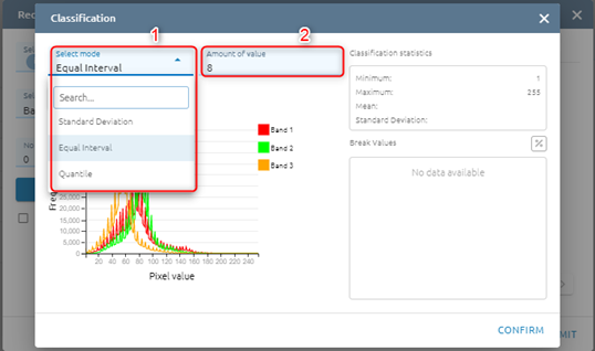
Step 3: Type input:
Select mode
Standard Deviation: the method shows you how much a feature’s attribute value varies from mean. Class breaks are created with equal value ranges that percentage of the standard deviation using mean value and the standard deviation from the mean
Equal interval: the method divides the range of values into equal-sized subranges.
Quantile: the method will assign the same number of values to each class. There are no empty classes or classes with too few or too many values. This method works well with the linearly distributed data.
Type Amount of value (If mode is Standard Deviation, the default Amount of value will be 6)
Step 4: Click Classify button
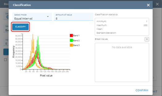
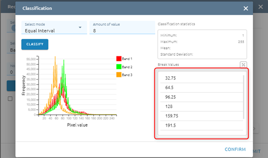
After click Classify button, please see Histogram and Break Values based mode and amount of value
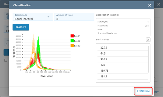
Step 5: Click Confirm button
Step 6:
You can add Max value - Min value - Value
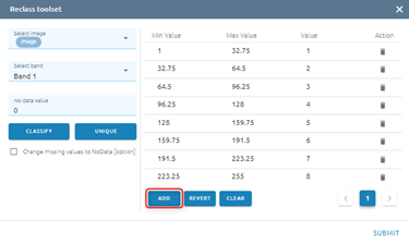
Type new data
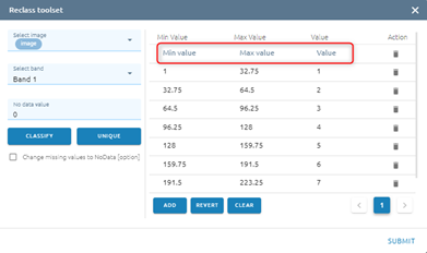
or you can edit by type directly or delete
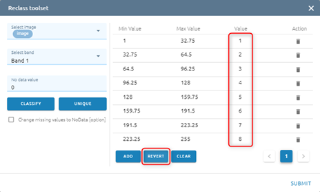
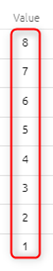
You can Revert values
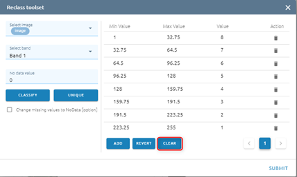
You can Clear all values
Default: No data value equal 0. If you want to change No data value, type input directly. And click checkbox if you want to change miss value to No data
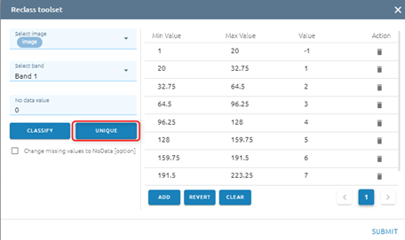
Click Unique if you want each old value to correspond to a unique new value
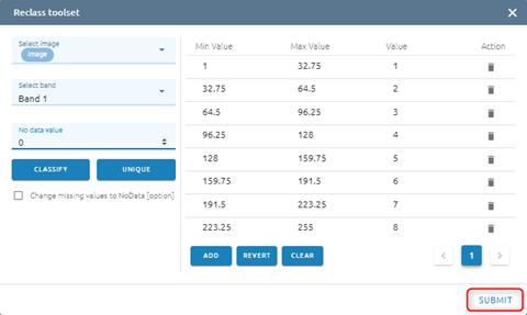
Step 7: Click Submit button
Type name -> Click Confirm button
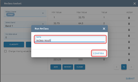
=> Tasks will be created in Tasks. Wait task was successful, please check at Imagery with the correct name.
Tools
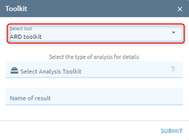
ARD Toolkit
ARD Toolkit includes the tools for analysing image(s).
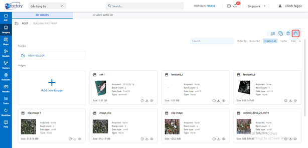
Click  icon to start use tools:
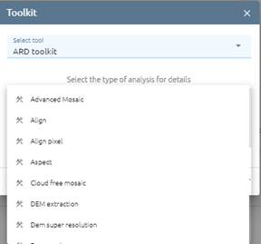
Select tool:
Select type ARD:
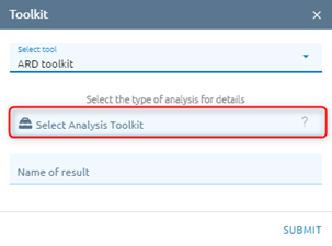
For more informations about tool, click icon.
Advanced Mosaic
Recent remote sensing applications play more and more important roles in many fields such as environmental monitoring, disaster assessment or creating base map for land use land cover. Therefore, the analyzing remote sensing is moving from single image scene to regional mosaics which require several image scenes. However, the quality of mosaic image depends on the radiometric and geometric characteristics of individual image. Understanding that, with growing requirements of this techniques, EOFactory provide a mosaic tool to merge many satellite or aerial images together. This tool support merge/ combination list of images into a single image automatically.
Type Name of image result.
Select destination folder to store result.
Select images from list images (type input to search image)
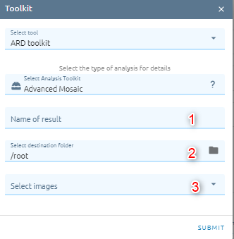
Click Submit button and Confirm to pay cost

=> Task will be created. When task is success, please check result in menu Imagery
Align Pixel
This tool is able to take several rasters as input and to align them perfectly, that means:
Reproject to the same CRS,
Resample to the same cell size and offset in the grid,
Clip to a region of interest,
Rescale values when required.
Type Name of image result.
Select destination folder to store result.
Select image from images list (type input to search image).
Select reference image from images list.
Click Submit button and Confirm to pay cost
Aspect
Generates an aspect map from any GDAL-supported elevation raster. Aspect is the compass direction that a slope faces. The pixels will have a value from 0-360° measured in degrees from north indicating the azimuth. On the northern hemisphere, the north side of slopes is often shaded (small azimuth from 0°-90°), while the southern side receives more solar radiation (higher azimuth from 180°-270°). Calculates the aspect of the Digital Terrain Model in input. The final aspect raster layer contains values from 0 to 360 that express the slope direction, starting from north (0°) and continuing clockwise.
Type name of image result.
Select destination folder to store result.
Select image from images list (only one image).
Choose option(s). There are 4 options:
Trigonometric: trigonometric angle instead of azimuth. Thus 0° means East, 90° North, 180° West, 270° South
Zero for flat:Return 0 for flat areas with slope=0, instead of -9999
Compute Edges: Generates edges from the elevation raster
Use Zevenbergen Thorne formula instead of the Horn’s one: The literature suggests Zevenbergen & Thorne to be more suited to smooth landscapes
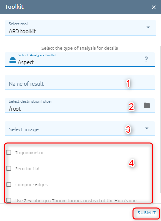
Click Submit button and Confirm to pay cost
Atmosphere
Atmosphere tool will help users remove atmosphere from image.
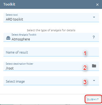
Type name of image result.
Select destination folder to store result.
Select image from images list (contain raw reference).
Click Submit button and Confirm to pay cost
Cloud Free Mosaic
It will help users remove clouds in an area if there are collections of overlapping images.
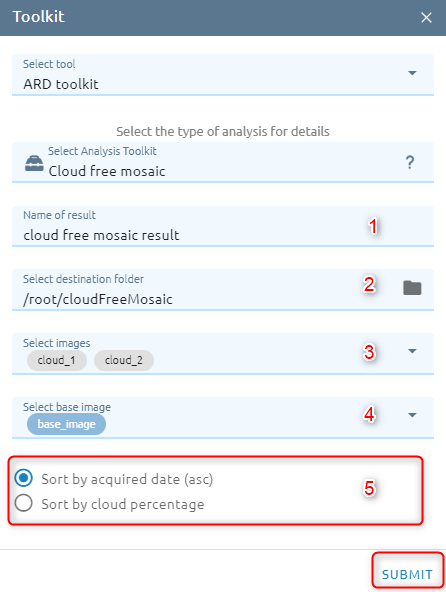
Type name of image result.
Select destination folder to store result.
Select images from images list (images must overlap).
Select base image from images list.
Select option. There are two options:
Sort by acquired date (asc) (default)
Sort by cloud percentage
Click Submit button and Confirm to pay cost
Dem Extraction
A DSM (also referred to as a DEM) extracted from stereo images represents the earth’s surface and includes all objects on it.
Type name
Select destination folder to store result
Select images: select stereo images
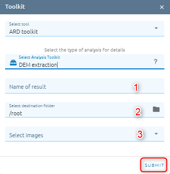
Click Submit button and Confirm to pay cost.
Down Scale
Improve the resolution of the image from low to high resolution.
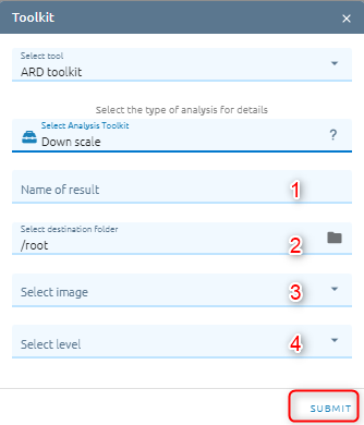
Type name of image result.
Select destination folder to store result.
Select image from images list.
There are two level:
2: means an increase in spatial resolution in double. For example from resolution 10m, downscale will improve the spatial resolution to 5m.
4: means increasing in spatial resolution four times.
Click Submit button and Confirm to pay cost.
Hillshade
This algorithm calculates the hillshade of the Digital Terrain Model in input. The shading of the layer is calculated according to the sun position (azimuth and elevation).
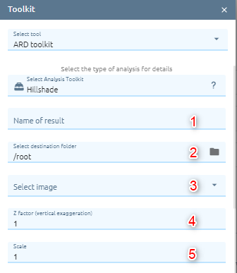
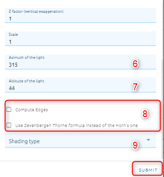
Type name of image result.
Select destination folder to store result.
Select image: dem image from images list.
Type Z factor: Vertical exaggeration used to pre-multiply the elevations.
Type scale: Ratio of vertical units to horizontal. If the horizontal unit of the source DEM is degrees (e.g Lat/Long WGS84 projection), you can use scale=111120 if the vertical units are meters (or scale=370400 if they are in feet).
Type Azimuth of the light:Azimuth of the light, in degrees. 0 if it comes from the top of the raster, 90 from the east, …
Type Altitude of the light: Altitude of the light, in degrees. 90 if the light comes from above the DEM, 0 if it is raking light.
Select option (optional). There are two options:
Compute Edge: Generates edges from the elevation raster.
Use Zevenbergen Thorne formula instead of the Horn’s one: Activates Zevenbergen&Thorne formula for smooth landscapes.
Select Shading type:
Combined: combined shading, a combination of slope and oblique shading.
Multidirectional: multidirectional shading, a combination of hill shading illuminated from 225 deg, 270 deg, 315 deg, and 360 deg azimuth.
Click Submit button and Confirm to pay cost.
Image Resampling
Resamples the input image or bitmap file and creates a new file of a different resolution.
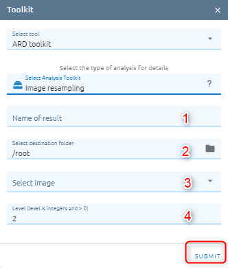
Type name of image result.
Select destination folder to store result.
Select image from images list.
Type level: (if you choose level 2, the spatial resolution will decrease double for example raw data has 5m resolution, after resampling with level 2, the resolution will be 10m).
Click Submit button and Confirm to pay cost.
Mosaic
This tool supports merge/ combination list of images into a single image automatically. It is similar to advanced mosaics with different algorithms. It’s more reliable when you have different subsets of the same date.
Orthorectify
Orthorectify is the process of removing the effects of terrain and sensor creating a planimetrically correct image. The image will match the spatial by considering location, elevation and sensor information.
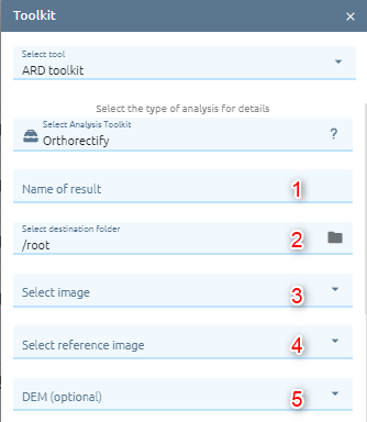
Type name of image result.
Select destination folder to store result.
Select image from images list.
Select reference image from images list.
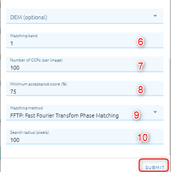
Select DEM image (optional)
Type Matching band
Type Number of GCPs: the number of points that you want to collect over each image.
Type Minimum acceptance score: enter a value from 0-1 which defines the minimum correlation score that will be considered a successful match.
Select Matching method. There are two methods:
FFTP: Fast Fourier Transform Phase Matching: when two images have a relative shift between them, the result is a phase difference in the Fourier domain. FFTP determines the shift between images using this phase difference.
NCC: Normalized Cross Correlation. This method finds the relative shift between two images by finding the shift that produces the maximum cross-correlation coefficient of the gray values in the images.
Type Search radius: a number to define the search radius around the kernel.
Click Submit button and Confirm to pay cost.
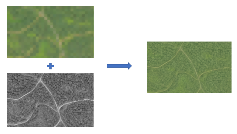
Pansharpening
PANSHARP creates high-resolution color images by fusing black-and-white panchromatic and multispectral color images. This image fusion technique is known as pansharpening and supports 8-bit, 16-bit, or 32-bit real data types. PANSHARP can fuse images obtained from the same sensor or from different sensors.
Example:
Type name of image result.
Select destination folder to store result.
Select multispectral image from images list.
Select panchromatic image from images list.
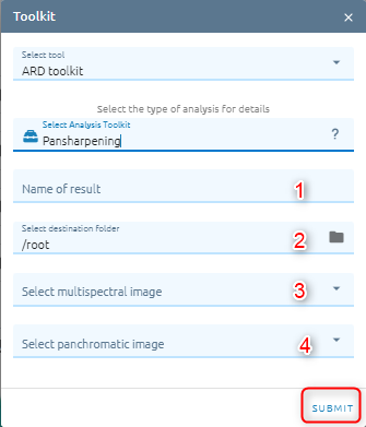
Click Submit button and Confirm to pay cost.
Raster Clip
Clip the raster using features of an polygon layer. Only the areas in the raster that fall within the polygons of the mask layer will be added to the resulting layer.
Type name of image result.
Select destination folder to store result.
Select image which need to clip.
Select mask layer: includes aoi data or vector data.
Check option
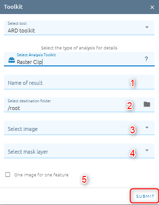
Click Submit button and Confirm to pay cost.
Slope
Calculate the slope from the DEM image. The slope is the angle of inclination of the terrain and is expressed in degrees
Type name of image result.
Select destination folder to store result.
Select image from images list.
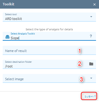
Click Submit button and Confirm to pay cost.
Stack
Layer stacking is a process for combining multiple images with same extent into a single image.
Type name of image result.
Select destination folder to store result.
Select images from images list.
Select bands which you want to merge: click Band selection to open popup.
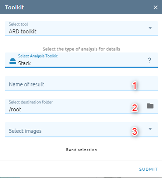
Click Submit button and Confirm to pay cost.
Visual Imagery
To convert an image to data type unit 8 with reference image or not.
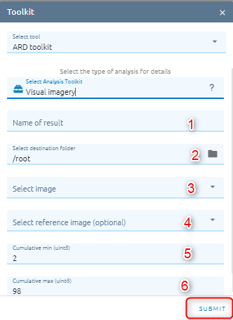
Type name of image result.
Select destination folder to store result.
Select image from images list.
Select reference image from images list.
Type cumulative min (min stretch)
Type cumulative max (max stretch)
Click Submit button and Confirm to pay cost.
Zonal
Calculates statistics on values of a raster within the zones of another dataset.
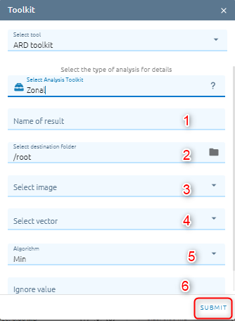
Type name: name of image result.
Select destination folder to store result
Select image from images list.
Select vector from vectors list.
Select Algorithm. There are 4 options:
Min: Determines the smallest value of all cells in the value raster that belong to the same zone as the output cell
Mean: Determines the mean of all cells in the value raster that belong to the same zone as the output cell
Max: Determines the largest value of all cells in the value raster that belong to the same zone as the output cell
Most value: Determines the most value of all cells in the value raster that belong to the same zone as the output cell
Type Ignore value: value which want to ignore in processing.
Click Submit button and Confirm to pay cost.
Super Registration
The super registration can co-register images with up to 1/10th of a pixel accuracy to reduce the risk of misalignment errors. When two ortho images are laid on top of each other they should, in theory, perfectly align.In particularly bad cases this shift can be many pixels. This misalignment can be caused by poor math models (e.g. inaccurate GCPs), a low quality elevation model or distortions in the camera lens.
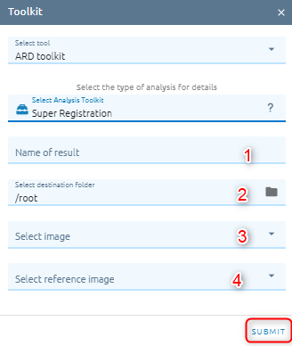
Type name of image result.
Select destination folder to store result.
Select image from images list.
Select reference image from images list.
Click Submit button and Confirm to pay cost.
Scout Index Analysis
This tool used to calculate NDVI (Normalized Difference Vegetation Index), SIPI (Structure Insensitive Pigment Index), SAVI (Soil Adjusted Vegetation Index), EVI (Enhanced Vegetation Index), PSRI (Plant Senescence Reflectance Index), and CI (Chlorophyll Index) of image.
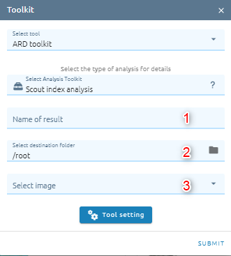
Type name of image result.
Select destination folder to store result.
Select image from images list.
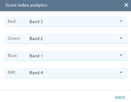
Click Tool setting: select correspond band
Click Submit button and Confirm to pay cost.
DEM Super Resolution
DEM Super Resolution is a process of producing a high-resolution image from one or more low-resolution images.
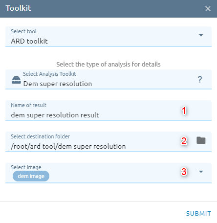
Type name of image result.
Select destination folder to store result.
Select DEM image from images list.
Click Submit button and Confirm to pay cost.
Contour
Creates a vector segment containing contour lines from a raster image, such as an elevation (DEM) image, given a specified contour interval. The contour value for each line is saved in either the z-coordinate of all vertices or in a separate attribute field.
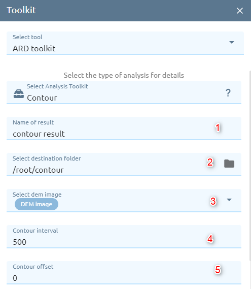
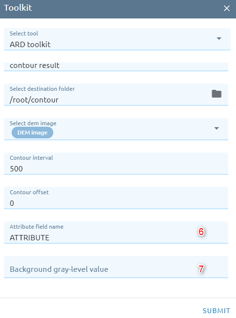
Type name of vector result.
Select destination folder to store result.
Select DEM image from images list.
Type Contour interval
Type Contour offset: must be a value between zero and the specified interval value; the default is 0.0.
Type Attribute field name: specifies the name of the double-precision field in which the contour value is stored.
There are three options:
ATTRIBUTE: uses the field named “ATTRIBUTE” in vector segment.
ZCOORD: uses the actual z-coordinates of the vectors.
<field>: uses the specified numerical field.
Type Background gray-level value: specifies the background elevation (NO DATA) value in the input raster or DEM elevation image.
Click Submit button and Confirm to pay cost.
SLASP
Calculates the surface slope and aspect angles for each pixel of an elevation. The values in the slope result range between 0 and 90 degrees, and are used to describe the angle of incline or decline at a given pixel. The values in the aspect result describe the direction in which the slopes are facing. These orientation angles range from 0 to 360 degrees, where 0 degrees represents the top (usually North) and 90 degrees represents the right side (usually East). Pixels without slope (0 degrees) are assigned a special “no aspect” value.
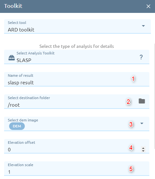
Type name of images result.
Select destination folder to store result.
Select DEM image from images list.
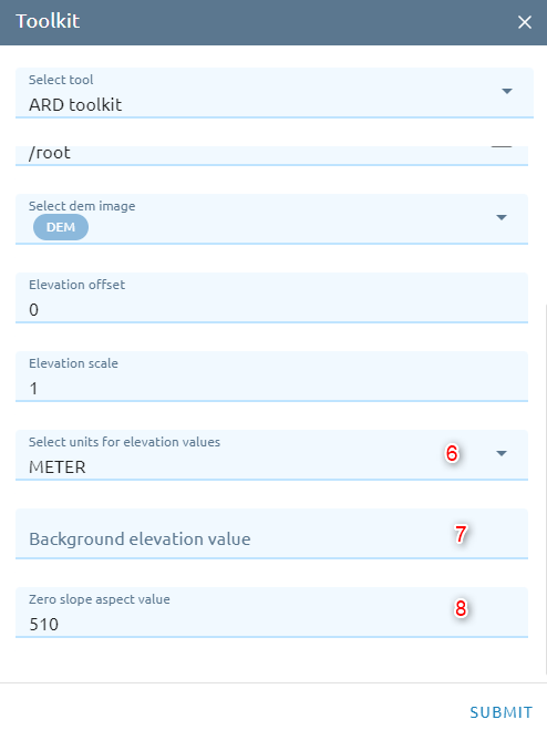
Type Elevation offset: specifies the values used to shift the DEM pixel values to values in the units indicated by the Elevation Units parameter.
Type Elevation scale: specifies the values used to scale the DEM pixel values to values in the units indicated by the Elevation Units parameter.
Select Unit: Specifies the units used to describe the elevation values of the input DEM file.
Type Background elevation value: Specifies a special value, in the input elevation channel, used to indicate which pixel value is to be handled as no data (no elevation).
Type Zero slope aspect value: specifies the digital value assigned to pixels in the output aspect map, where slope is 0 (No slope). If this parameter is not specified, these pixels are assigned a value of 510.
Click Submit button and Confirm to pay cost.