Tools
Buffer
This algorithm computes a buffer area for all the features in an input layer, using a fixed or dynamic distance. The segments parameter controls the number of line segments to use to approximate a quarter circle when creating rounded offsets. The end cap style parameter controls how line endings are handled in the buffer. The join style parameter specifies whether round, miter or beveled joins should be used when off setting corners in a line. The miter limit parameter is only applicable for miter join styles, and controls the maximum distance from the offset curve to use when creating a mitered join.
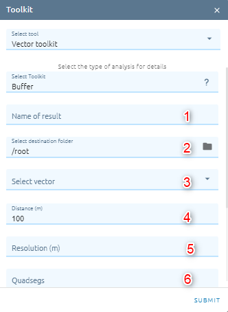
Step 1: Type input:
Type Name
Select destination folder to contain result
Select Vector from Vectors list
Type Distance (default: 100m)
Type Resolution
Type Quadsegs which controls the number of line segments to use to approximate a quarter circle when creating rounded offsets.
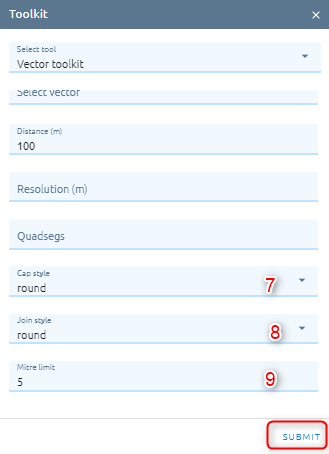
Select Cap style (default: round): controls how line endings are handled in the buffer.
Select Join style (default: round): Specifies whether round, miter or beveled joins should be used when offsetting corners in a line
Type Mitre limit (default: 5): Controls the maximum distance from the offset curve to use when creating a mitered join (only applicable for miter join styles). Minimum: 1.
Step 2: Click “Submit” button
Centroid
Creates a new point layer, with points representing the centroids of the geometries of the input layer.
Step 1: Type input:
Type Name
Select destination folder to contain result
Select Vector from Vectors list
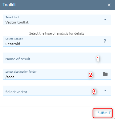
Step 2: Click “Submit” button
Rectify
A method that approximates the prediction pixels into polygons making decisions based on the whole prediction feature space.
Step 1: Type input:
Type Name
Select destination folder to contain result
Select Vector from Vectors list
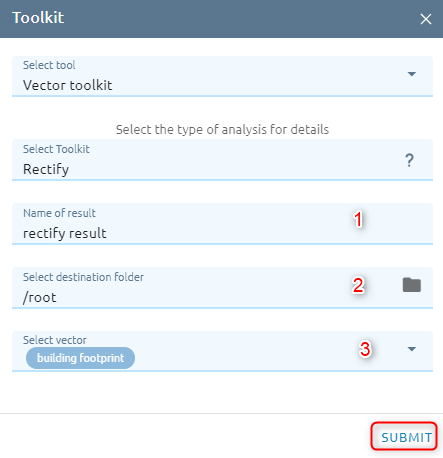
Step 2: Click “Submit” button
Row detection
Row detection is performed automatically for straight and curved rows. The detected rows are used in many applications.
Step 1: Type input:
Type Name
Select destination folder to contain result
Select Vector from Vectors list
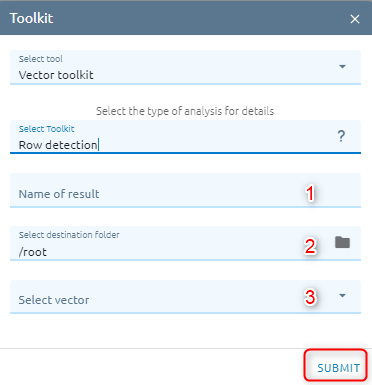
Step 2: Click “Submit” button
Simplify
Simplifies the geometries in a line or polygon layer. It creates a new layer with the same features as the ones in the input layer, but with geometries containing a lower number of vertices.
Step 1: Type input
Type Name
Select destination folder to contain result
Select Vector from Vectors list
Type Tolerance : if the distance between two nodes is smaller than the tolerance value, the segment will be simplified and vertices will be removed.
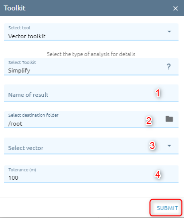
Step 2: Click “Submit” button
Vector Clip
This algorithm clips a vector layer using the features of an additional polygon layer. Only the parts of the features in the Input layer that fall within the polygons of the Overlay layer will be added to the resulting layer.
Step 1: Type input
Type Name
Select destination folder to contain result
Select Vector from Vectors list
Select AOI from AOIs list
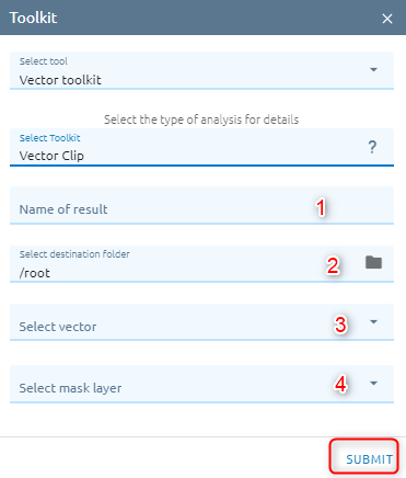
Step 2: Click “Submit” button
Update
Computes a geometric intersection of the input features and update features. The attributes and geometry of the input features are updated by the update features in the output feature class
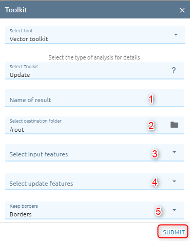
Step 1: Type input
Type Name
Select destination folder to contain result
Select vector from Vectors or layer from Layers Control. The input features must be polygon.
Select vector from Vectors or layer from Layers Control. The update features must be polygon.
Select Keep borders: If option Borders is checked (default), the outside border of the update features will be kept in the output. Else if option No borders is checked, the outside border of the update features are dropped after they are inserted into the input features. Item values of the update features take precedence over input features attributes.
Step 2: Click “Submit” button
After task is successful, check vector in Vectors menu.
Union
Computes a geometric union of the input features. All features and their attributes will be written to the output.
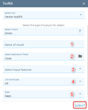
Step 1: Type Input
Type Name
Select destination folder to contain result
Select vectors from Vectors or layers from Layers Control. The input features must be polygon.
Select Join attributes to determines which attributes from the input features will be transferred to the output.
Select Gaps option to gaps are areas in the output that are completely enclosed by other polygons (Gaps — No feature will be created for areas in the output that are completely enclosed by polygons. This is the default.**No gaps** — A feature will be created for the areas in the output that are completely enclosed by polygons. This feature will have blank attributes and its FID values will be -1).
Step 2: Click “Submit” button
After task is successful, check vector in Vectors menu.
Intersect
Computes a geometric intersection of the input features. Features or portions of features which overlap in all layers and/or feature classes will be written to the output.
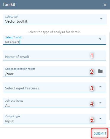
Step 1: Type Input
Type Name
Select destination folder to contain result
Select input features is vector from Vectors or layer from Layers Control.
Select Join attributes option to determines what attributes will be transferred to the output.
Select Output type option to choose what type of intersection you want to find.
Step 2: Click “Submit” button
After task is successful, check vector in Vectors menu.
Symmetrical Difference
Features or portions of features in the input features and update features that do not overlap will be written to the output.
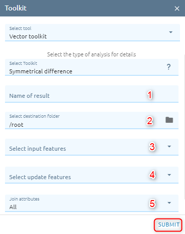
Step 1: Type Input
Type Name
Select destination folder to contain result
Select input features is vector from Vectors or layer from Layers Control.
Select erase features is vector from Vectors or layer from Layers Control.
Select Join attributes option to determines what attributes will be transferred to the output.
Step 2: Click “Submit” button
After task is successful, check vector in Vectors menu.
Erase
Creates a feature class by overlaying the input features with the polygons of the erase features. Only those portions of the input features falling outside the erase features outside boundaries are copied to the output.
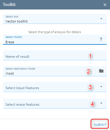
Step 1: Type Input
Type Name
Select destination folder to contain result
Select input features is vector from Vectors or layer from Layers Control.
Select erase features is vector from Vectors or layer from Layers Control.
Step 2: Click “Submit” button
After task is successful, check vector in Vectors menu.
Identity
Computes a geometric intersection of the input features and identity features. The input features or portions thereof that overlap identity features will get the attributes of those identity features.
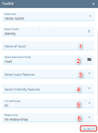
Step 1: Type Input
Type Name
Select destination folder to contain result
Select input features is vector from Vectors or layer from Layers Control.
Select identity features is vector from Vectors or layer from Layers Control. Identity features must be polygons or have the same geometry type as the input features.
Select Join attributes option to determines what attributes will be transferred to the output.
Select Relationship option to determines if additional spatial relationships between the input features and the identity features are to be written to the output. This only applies when the input features are lines and the identity features are polygons.
Step 2: Click “Submit” button
After task is successful, check vector in Vectors menu.
Spatial Join
Joins attributes from one feature to another based on the spatial relationship. The target features and the joined attributes from the join features are written to the output feature class.
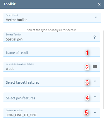
Step 1: Type input:
Type Name
Select destination folder to contain result
Select target features (Attributes of the target features and the attributes from the joined features are transferred to the output feature class. However, a subset of attributes can be defined in the field map parameter)
Select join features
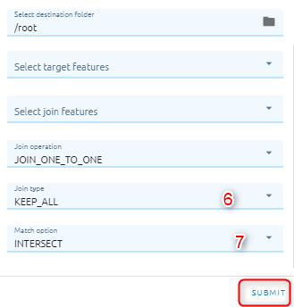
Select join operation to specifies how joins between the target features and join features will be handled in the output feature class if multiple join features are found that have the same spatial relationship with a single target feature (JOIN_ONE_TO_ONE — If multiple join features are found that have the same spatial relationship with a single target feature, the attributes from the multiple join features will be aggregated using a field map merge rule. JOIN_ONE_TO_MANY — If multiple join features are found that have the same spatial relationship with a single target feature, the output feature class will contain multiple copies (records) of the target feature.)
Select match option to specifies the criteria used to match rows.
Step 2: Click “Submit” button
After task is successful, check vector in Vectors menu.
Raster map
Add new attribute to the vector result which determines the most value of all cells in the value raster that belong to the same zone as the output cell.
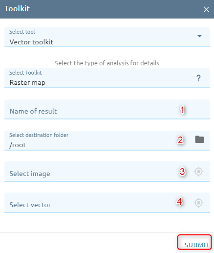
Type Name
Select destination folder to contain result
Select image
Select vector